In critical industries such as oil & gas, petrochemical, offshore, power generation, and structural fabrication, weld integrity directly affects operational safety and asset reliability. A minor internal defect like lack of fusion or crack can lead to pressure loss, leakage, structural collapse, or catastrophic failure.
For decades, inspection relied on Visual Testing (VT), Radiographic Testing (RT), and conventional Ultrasonic Testing (UT). While these methods remain relevant, increasing quality standards, tighter code compliance, and demand for digital traceability have accelerated adoption of advanced ultrasonic technologies.
One of the most powerful and widely adopted modern inspection techniques is Phased Array Ultrasonic Testing (PAUT).
Phased Array Ultrasonic Testing (PAUT) is an advanced ultrasonic method that uses multiple probe elements with electronically controlled time delays to steer, focus, and scan ultrasonic beams across a weld. It provides high-resolution imaging, precise defect sizing, faster inspection, and permanent digital records.
Today, PAUT is widely used in:
-
Pipeline girth weld inspection
-
Pressure vessels and boilers
-
Offshore platform fabrication
-
Refinery shutdown inspection
-
Nuclear and power plant components
-
Structural steel projects
This comprehensive guide covers PAUT from A to Z — working principle, equipment, procedure, defect detection capability, comparison with UT and RT, standards, certification, and cost factors — in technical depth suitable for welding professionals.
What is PAUT in Welding?
PAUT stands for Phased Array Ultrasonic Testing. It is a non-destructive testing (NDT) method that uses an array of ultrasonic elements in a single probe. Each element can be pulsed independently with calculated time delays. These delays allow the ultrasonic beam to be electronically steered at different angles and focused at different depths.
Unlike conventional UT, where each probe has a fixed angle (45°, 60°, 70°), PAUT can generate multiple angles from a single probe position. This significantly improves weld coverage and defect characterization.
In weld inspection, PAUT is primarily used to detect:
-
Lack of fusion (LOF)
-
Lack of penetration (LOP)
-
Cracks
-
Slag inclusions
-
Porosity
-
Lamination
Working Principle of PAUT
Ultrasonic Wave Fundamentals
Ultrasonic testing uses high-frequency sound waves, typically between 2 MHz and 10 MHz. These waves travel through solid materials and reflect when encountering boundaries or discontinuities.
Key physical principles involved:
-
Acoustic impedance mismatch
-
Reflection and refraction
-
Snell’s law
-
Time-of-flight measurement
-
Amplitude evaluation
When the sound wave encounters a defect inside the weld, part of the wave reflects back to the probe. The instrument measures the time taken for the echo to return and calculates defect depth and location.
Phasing and Beam Steering Concept
The defining feature of PAUT is electronic beam control.
A phased array probe contains multiple small ultrasonic elements arranged in a line (linear array) or grid (matrix array). Each element is pulsed with a slight time delay relative to adjacent elements.
By controlling these delays:
-
The beam angle can be changed electronically.
-
The focal depth can be adjusted dynamically.
-
Multiple angles can be scanned without physically moving the probe.
This process is called sectorial scanning (S-scan).
For weld inspection, common angle ranges include 40° to 70°, depending on weld geometry and thickness.
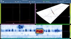
PAUT Data Display Modes
PAUT provides multiple imaging formats, which significantly enhance defect visualization compared to conventional UT.


-
A-Scan – Basic amplitude vs time signal.
-
B-Scan – Cross-sectional side view of weld.
-
C-Scan – Plan view mapping of inspection area.
-
S-Scan (Sectorial Scan) – Multi-angle cross-sectional imaging of weld.
The S-scan is especially valuable for weld inspection because it provides a real-time cross-sectional visualization of the weld volume.
Components of a PAUT System
A complete PAUT inspection system consists of several critical components.
1. PAUT Instrument
Modern PAUT instruments include:
-
Multi-channel pulser/receiver
-
High-resolution display
-
Real-time imaging software
-
Data acquisition system
-
Storage for digital records
Advanced systems allow encoding and automated scanning.
2. Phased Array Probe


-
Linear array (most common for welds)
-
Matrix array (3D capability)
Typical characteristics:
-
16–64 elements
-
Frequency range: 2–10 MHz
-
Element pitch designed for beam resolution
3. Wedges
Wedges are used to:
-
Introduce sound at a specific angle
-
Control refracted angle
-
Improve coupling
Selection depends on material velocity and weld geometry.
4. Scanner and Encoder
Scanning systems may be:
-
Manual
-
Semi-automated
-
Fully automated
Encoders track probe movement and allow accurate defect positioning.
Couplant
Couplant ensures proper transmission of ultrasonic energy from probe to material. Water-based gel is commonly used.
Step-by-Step PAUT Inspection Procedure for Welding
A detailed procedure ensures reliable and code-compliant results.
Step 1: Pre-Inspection Preparation
-
Review drawing and WPS
-
Confirm applicable code (ASME, API, AWS, ISO)
-
Identify weld type and thickness
-
Clean surface (remove scale, spatter)
-
Select calibration block
Step 2: Equipment Calibration
Calibration is performed according to codes such as ASME Section V and ISO 13588.
Calibration includes:
-
Velocity calibration
-
Wedge delay calibration
-
Sensitivity calibration
-
Distance Amplitude Correction (DAC)
-
Time Corrected Gain (TCG)
Proper calibration ensures accurate depth and amplitude measurement.
Step 3: Focal Law Setup
Parameters defined:
-
Angle range (e.g., 45°–70°)
-
Focal depth
-
Number of active elements
-
Scanning resolution
Step 4: Scanning the Weld
-
Apply couplant
-
Position probe on weld crown or toe
-
Perform encoded scan
-
Monitor S-scan image
-
Ensure complete weld coverage
Step 5: Data Interpretation
Defects are evaluated based on:
-
Signal amplitude
-
Position relative to weld centerline
-
Length sizing
-
Height estimation
Acceptance criteria are defined by codes such as:
-
API 1104
-
AWS D1.1
-
ASME Section VIII
Step 6: Reporting
Inspection report includes:
-
Weld identification
-
Equipment used
-
Calibration details
-
Defect location and size
-
Acceptance or rejection status
-
Code reference
Digital data is stored for traceability.
Types of Weld Defects Detected by PAUT
PAUT is highly effective in detecting planar and volumetric defects.
1. Lack of Fusion (LOF)
Occurs when weld metal fails to fuse with base metal. PAUT detects LOF effectively due to beam steering capability.
2. Lack of Penetration (LOP)
Detected near weld root using low-angle beams.
3. Cracks
Planar cracks reflect strong signals and are clearly visible in S-scan.
4. Slag Inclusions
Irregular reflectors appearing in weld metal.
5. Porosity
Volumetric defects producing scattered signals.
PAUT is generally superior to radiography for detecting planar defects.
PAUT vs Conventional UT vs Radiographic Testing
PAUT vs Conventional UT
Advantages of PAUT:
-
Multi-angle scanning
-
Higher probability of detection
-
Improved defect sizing
-
Faster coverage
-
Digital data recording
Conventional UT advantages:
-
Lower equipment cost
-
Simpler operation
PAUT vs Radiographic Testing
Radiographic Testing uses X-rays or gamma radiation.
Comparison factors:
-
Radiation hazard: RT requires exclusion zone; PAUT does not.
-
Planar defect detection: PAUT is superior.
-
Environmental impact: PAUT safer.
-
Digital archiving: Both possible, but PAUT offers immediate imaging.
-
Thickness limitation: PAUT handles thicker sections efficiently.
Many industries now replace RT with PAUT for pipeline welds.
Advantages of PAUT in Welding Inspection
-
High defect detection accuracy
-
Excellent sizing capability
-
Electronic beam steering
-
Reduced inspection time
-
No radiation hazards
-
Permanent digital record
-
Reduced downtime
-
High repeatability
Limitations of PAUT
-
Higher equipment cost
-
Skilled operator required
-
Complex setup
-
Surface condition sensitivity
-
Grain scattering issues in austenitic welds
Proper training mitigates most limitations.
PAUT for Special Weld Applications
Austenitic Stainless Steel Welds
Due to coarse grain structure, sound scattering increases. Lower frequency probes and advanced focal laws are required.
Dissimilar Metal Welds
Requires customized setup due to acoustic mismatch.
Pipeline Girth Welds

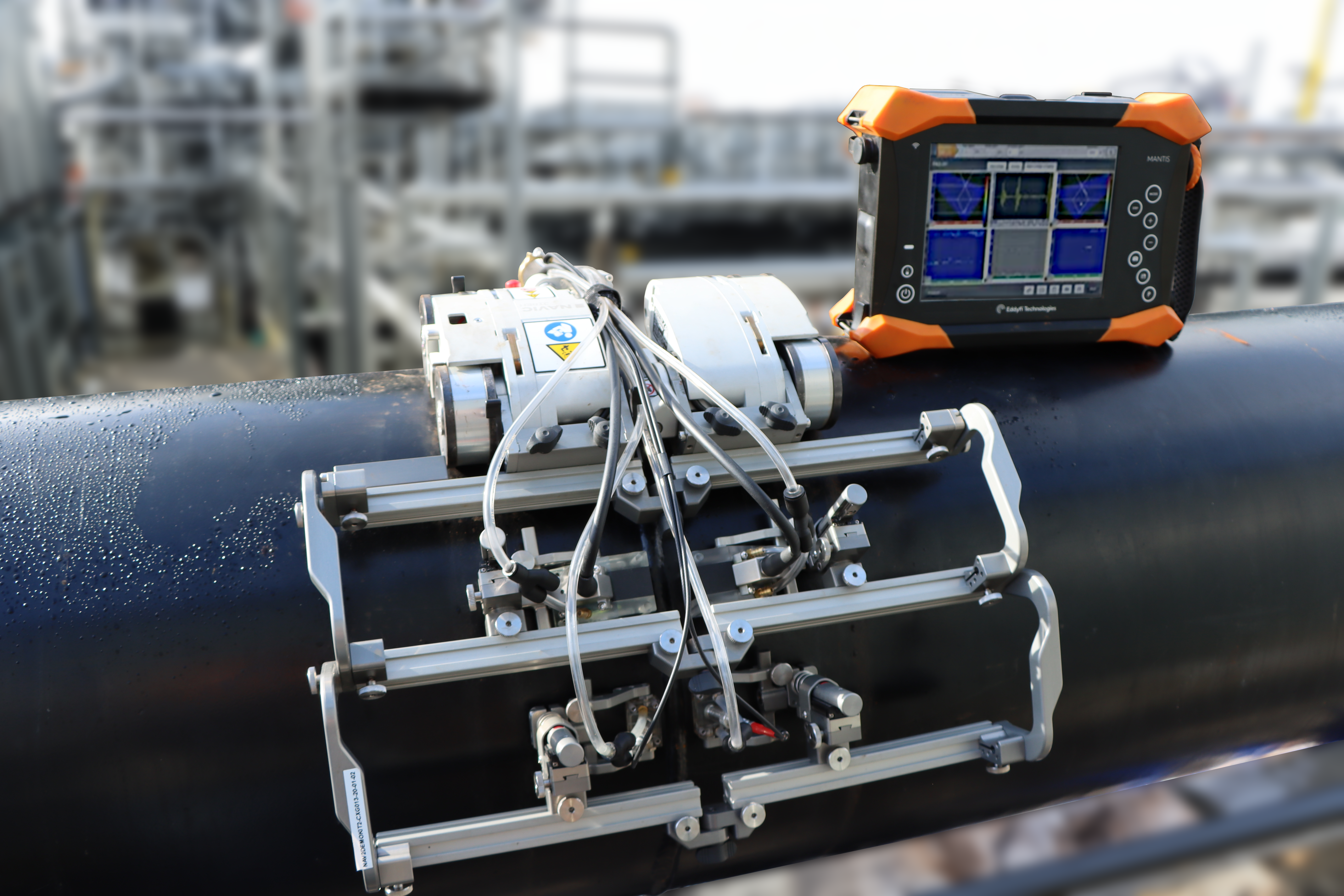
Automated PAUT systems are widely used for high-speed pipeline construction.
Codes and Standards for PAUT
Important codes governing PAUT include:
-
ASME Section V
-
ASME Section VIII
-
API 1104
-
AWS D1.1
-
ISO 13588
These standards define qualification, calibration, and acceptance criteria.
PAUT Qualification and Certification
Personnel qualification follows:
-
SNT-TC-1A
-
ISO 9712
Certification levels:
-
Level I – Perform testing
-
Level II – Interpret results
-
Level III – Procedure approval
Detailed Cost Factors of PAUT Test for Welding
PAUT inspection cost is influenced by multiple technical and logistical factors.
1. Weld Thickness
Thicker welds require:
-
Multiple scanning passes
-
Different focal laws
-
Longer inspection time
Inspection cost increases proportionally with thickness due to increased scanning complexity.
2. Weld Length
Longer weld seams increase:
-
Scanning time
-
Data volume
-
Reporting workload
Pipeline projects with kilometers of welds use automated PAUT to reduce cost per weld.
3. Accessibility
Difficult access conditions such as:
-
Elevated locations
-
Confined spaces
-
Offshore environments
Increase labor and setup time.
4. Automation Level
Manual scanning is less expensive per day but slower. Automated encoded scanning increases equipment cost but reduces per-weld inspection time.
5. Code Requirements
Stricter codes such as nuclear or pressure vessel standards require:
-
Additional calibration
-
Increased documentation
-
Higher qualified personnel
This increases overall inspection cost.
6. Project Location
Remote locations require mobilization cost, equipment transport, and technician accommodation.
7. Reporting and Data Archiving
Digital data processing, analysis, and archiving add time and cost but increase traceability.
Future of PAUT in Welding Inspection
The industry trend indicates increasing automation and digital integration.
Future developments include:
-
Robotic scanning systems
-
AI-assisted defect recognition
-
Real-time cloud reporting
-
Integration with digital twins
-
Fully automated pipeline welding lines
PAUT is expected to become a primary weld inspection method in many industries.
Frequently Asked Questions
What is PAUT in welding?
PAUT is an advanced ultrasonic testing method using multi-element probes with electronic beam steering to detect weld defects.
Is PAUT better than RT?
For planar defects and safety considerations, PAUT is often superior to radiographic testing.
What defects can PAUT detect?
Cracks, lack of fusion, lack of penetration, porosity, slag inclusions, and laminations.
Is PAUT safe?
Yes. It uses sound waves and does not involve radiation.
What is S-scan in PAUT?
S-scan is a sectorial scan image showing multiple beam angles in a weld cross-section.
Conclusion
PAUT test for welding represents a significant advancement in non-destructive examination technology. It combines high detection accuracy, digital traceability, safety, and efficiency. When performed according to applicable standards and by certified personnel, PAUT ensures weld integrity, compliance, and long-term structural reliability.
For modern welding inspection programs, PAUT is no longer optional—it is increasingly becoming the preferred industry standard.